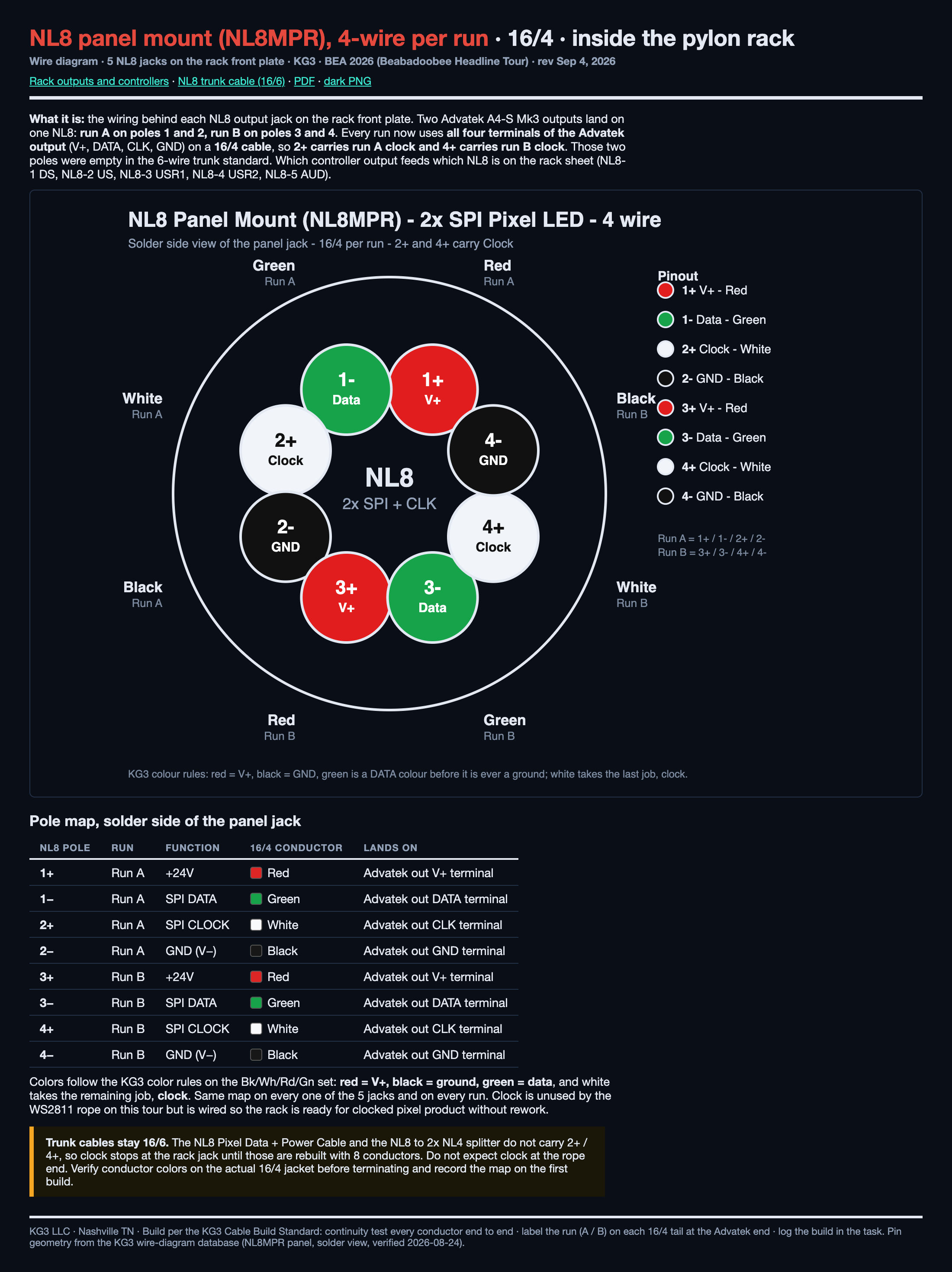
What it is: the wiring behind each NL8 output jack on the rack front plate. Two Advatek A4-S Mk3 outputs land on one NL8, each on its own 16/3 SOOW cable: output 1 on poles 1+ / 1− / 2−, output 2 on poles 3+ / 3− / 4−. WHITE = V+, GREEN = SPI DATA, BLACK = GND.2+ and 4+ are NOT USED (no wire, no jumper). Same map on the NL8 trunk and on the NL8 to NL4 SPI Splitter: OUTPUT 1 = poles 1/2, OUTPUT 2 = poles 3/4.
Pole map, solder side of the panel jack
NL8 pole
Output
Function
16/3 conductor
Lands on
1+
Output 1
+24V (V+)
White
Advatek output 1 V+ terminal
1−
Output 1
SPI DATA
Green
Advatek output 1 DATA terminal
2+
NOT USED, no wire
2−
Output 1
GND (V−)
Black
Advatek output 1 GND terminal
3+
Output 2
+24V (V+)
White
Advatek output 2 V+ terminal
3−
Output 2
SPI DATA
Green
Advatek output 2 DATA terminal
4+
NOT USED, no wire
4−
Output 2
GND (V−)
Black
Advatek output 2 GND terminal
Function follows the pin, never the colour. If a jacket shows different colours, land by function and tell Kenny. Same map on every one of the 5 jacks.
Rule of record (Kenny, Sep 17 2026): this replaces the Sep 4 "16/4 with clock on 2+ / 4+" sheet. Nothing on this tour carries clock. Verify every conductor end to end before the rack ships.