BEA 2026 · pylon PXL CTRL rack
Rack outputs and controllers
How the rack goes in at the pylon base and what plugs where. Four Advatek PixLite A4-S Mk3 (CTRL A to D) drive all 14 outputs through 5 NL8 ports and 4 NL4 ports on the front. Version of record September 17, 2026.
Controllers4 x A4-S Mk3CTRL A, B, C, D. 4 outputs each, expand OFF. CTRL E is the road spare, not in the rack.
Outputs14 live5 x NL8 (two runs each) + 4 x NL4 (one run each). C out 4 and D out 4 spare.
Pixels3,765 px24 segments, WS2811 RGB, 20 px/m, 3 ch/px.
sACN41-69170 px per universe. 70-85 held for CTRL E. Clear from 86.
Network192.168.41.xGateway .1. CTRL A .41, B .42, C .43, D .44, E .45.
Power2 x UHP-1500-243,000 W capacity, 1,483 W load. About 12.9 A at 120 V on one TRUE1 feed.
Front panel: which port is which
| Rack port | Type | Carries | Goes to | px | Universes |
|---|---|---|---|---|---|
| NL8-1 | NL8 | leg a DS2 = CTRL A out 2 leg b DS3 = CTRL A out 3 | DS wire ropes | 738 | 44-46, 47-49 |
| NL8-2 | NL8 | leg a US5 = CTRL B out 3 leg b US6 = CTRL B out 4 | US wire ropes | 614 | 60-61, 62-63 |
| NL8-3 | NL8 | leg a USR1-2 = CTRL C out 2 leg b USR1-3 = CTRL C out 3 | USR1 | 196 | 65, 66 |
| NL8-4 | NL8 | leg a USR2-2 = CTRL D out 2 leg b USR2-3 = CTRL D out 3 | USR2 | 200 | 68, 69 |
| NL8-5 | NL8 | leg a AUD1 = CTRL A out 4 leg b AUD2 = CTRL B out 1 | Audience | 1143 | 50-53, 54-57 |
| NL4-1 | NL4 | DS1 = CTRL A out 1 | DS wire ropes | 369 | 41-43 |
| NL4-2 | NL4 | US4 = CTRL B out 2 | US wire ropes | 307 | 58-59 |
| NL4-3 | NL4 | USR1-1 = CTRL C out 1 | USR1 | 98 | 64 |
| NL4-4 | NL4 | USR2-1 = CTRL D out 1 | USR2 | 100 | 67 |
Setting the rack up
- Roll the rack to the pylon baseFront (outputs) faces the pylon feeders. Rear plate (TRUE1 + etherCON) faces the cable path from LX. Leave the rear open for air.
- AC inOne TRUE1 feed into TRUE1 IN on the rear plate. TRUE1 THRU is a pass-through for the next thing on the same circuit. Rack draws about 12.9 A at 120 V, so give it its own 20 A circuit.
- Network inetherCON from the LX sACN switch into the rear plate. The second etherCON loops the network on. Controllers are static: CTRL A .41, B .42, C .43, D .44 on 192.168.41.x.
- Plug the feeders by port labelEach NL8 trunk goes to its numbered NL8 port and splits to two NL4 tails at the top (leg a and leg b). Each NL4 single goes to its numbered NL4 port. The table below says which run is on which port. Match the port label on the rack to the label on the trunk.
- Power up and testPower the rack, then run the Advatek test pattern on each box (Advatek Assistant 3, red / green / blue). Every run should light in order from its rack end. If red and green are swapped on a run, change Color Order on all outputs of that box, never the patch.
- Hand off to the consoleConsole sends sACN universes 41-69. Patch of record is the DMX Patch Map in the tech kit. 70-85 stay clear for CTRL E.
- If a box diesSwap in CTRL E. Import the dead box's .conf from the Controller Update Package, set the IP to the dead box's address, move the output cables across in the same order. The patch does not change.
Every output
Read left to right: controller, output number on the box, the port on the rack front, the run it drives, its segments in data order, pixels and universes.
| Controller | Out | Rack port | Type | Run | Segments (data order) | px | Universes |
|---|---|---|---|---|---|---|---|
| CTRL A192.168.41.41 | 1 | NL4-1 | NL4 | DS1 | DS1-1 > DS1-2 | 369 | 41-43 |
| 2 | NL8-1 a | NL8 | DS2 | DS2-1 > DS2-2 | 369 | 44-46 | |
| 3 | NL8-1 b | NL8 | DS3 | DS3-1 > DS3-2 | 369 | 47-49 | |
| 4 | NL8-5 a | NL8 | AUD1 | AUD1-1 > AUD1-2 > AUD1-3 | 568 | 50-53 | |
| CTRL B192.168.41.42 | 1 | NL8-5 b | NL8 | AUD2 | AUD2-1 > AUD2-2 > AUD2-3 | 575 | 54-57 |
| 2 | NL4-2 | NL4 | US4 | US4-1 > US4-2 | 307 | 58-59 | |
| 3 | NL8-2 a | NL8 | US5 | US5-1 > US5-2 | 307 | 60-61 | |
| 4 | NL8-2 b | NL8 | US6 | US6-1 > US6-2 | 307 | 62-63 | |
| CTRL C192.168.41.43 | 1 | NL4-3 | NL4 | USR1-1 | USR1-1 | 98 | 64 |
| 2 | NL8-3 a | NL8 | USR1-2 | USR1-2 | 98 | 65 | |
| 3 | NL8-3 b | NL8 | USR1-3 | USR1-3 | 98 | 66 | |
| CTRL D192.168.41.44 | 1 | NL4-4 | NL4 | USR2-1 | USR2-1 | 100 | 67 |
| 2 | NL8-4 a | NL8 | USR2-2 | USR2-2 | 100 | 68 | |
| 3 | NL8-4 b | NL8 | USR2-3 | USR2-3 | 100 | 69 |
Inside the rack
Network and universes
| Device | IP | Universes | Note |
|---|---|---|---|
| CTRL A | 192.168.41.41 | 41-53 | 4 live outputs, 1675 px |
| CTRL B | 192.168.41.42 | 54-63 | 4 live outputs, 1496 px |
| CTRL C | 192.168.41.43 | 64-66 | 3 live outputs, 294 px |
| CTRL D | 192.168.41.44 | 67-69 | 3 live outputs, 300 px |
| CTRL E | 192.168.41.45 | 70-85 held | Road spare. Not in the rack, no live outputs. Import the failed box's .conf and set its IP to take over. |
| Gateway | 192.168.41.1 | Subnet 192.168.41.0/24. Laptop on a static address in the same subnet (for example .200). | |
| Media server / console | sACN 41-69 out, clear from 86 | sACN (E1.31), 170 px per universe, every output starts on a fresh universe at ch 1. |
NL8 jack wiring inside the rack, two SPI outputs per jack, 16/3
Behind each of the 5 NL8 jacks: two Advatek outputs, one 16/3 SOOW cable each. WHITE = V+, GREEN = SPI DATA, BLACK = GND. Output 1 on 1+ / 1- / 2-, output 2 on 3+ / 3- / 4-. 2+ and 4+ are NOT USED. Same map as the NL8 to NL4 SPI Splitter. Full sheet: printer-friendly page · PDF · dark PNG.
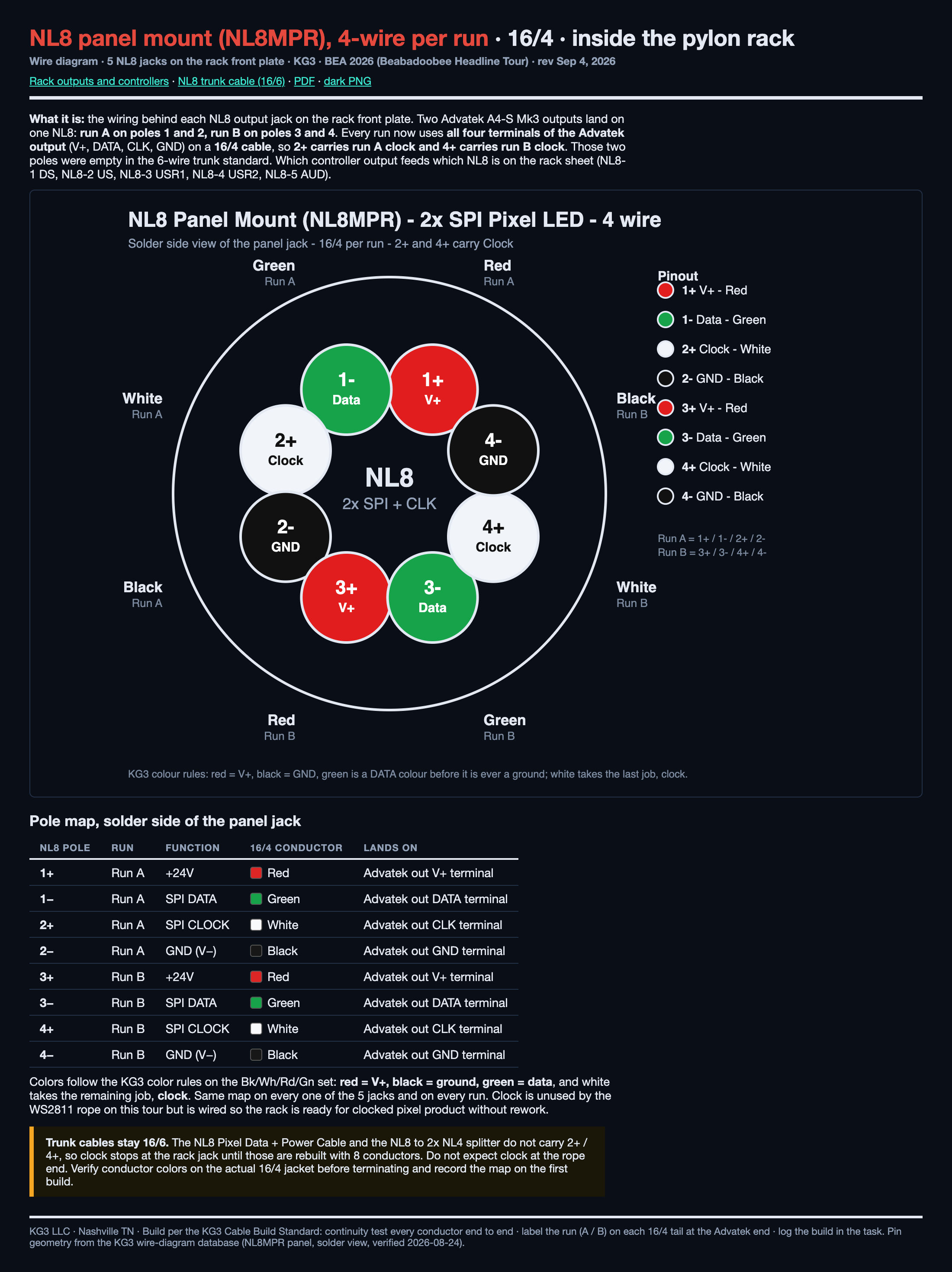
| NL8 pole | Output | Function | 16/3 wire |
|---|---|---|---|
| 1+ | Output 1 | V+ | White |
| 1- | Output 1 | DATA | Green |
| 2+ | NOT USED, no wire | ||
| 2- | Output 1 | GND | Black |
| 3+ | Output 2 | V+ | White |
| 3- | Output 2 | DATA | Green |
| 4+ | NOT USED, no wire | ||
| 4- | Output 2 | GND | Black |
Related
Controller Update Package (Rev 2) zip
.conf per controller (v1.9, firmware 3.15.0), README per box, output settings CSV, firmware file. Single files under Tech kit > Controller configs.
Patch by Controller pdf
One block per controller with universes.
Feeder Cable Map pdf
Rack to run feeders, what is used where.
NL8 to NL4 SPI Splitter
Leg a and leg b pinout.
NL8 Pixel Data + Power Cable
16/6, both ends.
Power and Data Plan
The rack in context with the drop chains.
KG3 · Beabadoobee 2026 Headline TourLED pixel neon package · rack sheet September 17, 2026